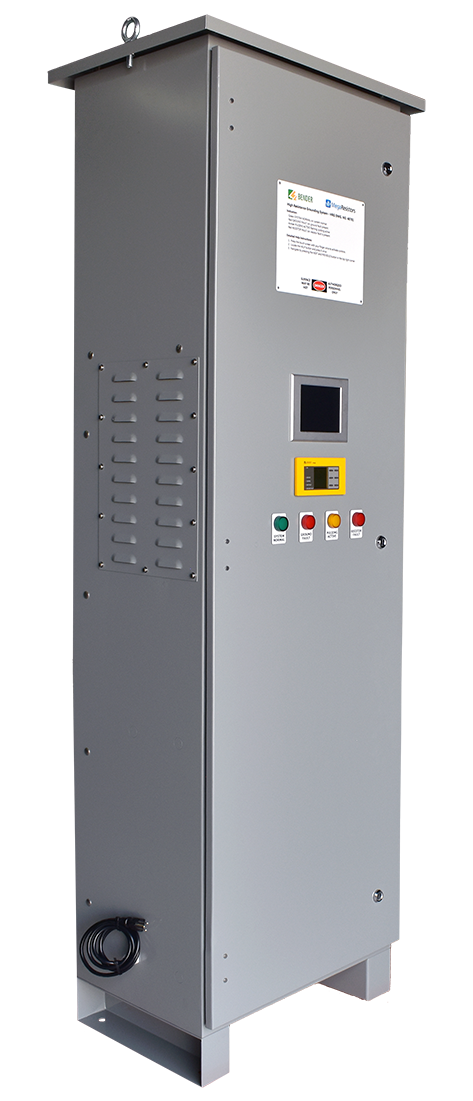
Advanced HRG
Our Advanced HRG is the most advanced high resistance grounding system in the market. It is designed to detect single or multiple ground faults in any number of feeders, and protect them either by maintaining continuity or tripping depending on their designated priority. With advanced communications capability, staff can monitor all systems from a remote dashboard accessible via their mobile device and receive all important alerts.
This product is best suited for any large installation with multiple feeders, and is the recommended choice when there are mission critical feeders or equipment in use. Scroll below to learn more about each of the unique features and configuration options.
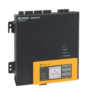
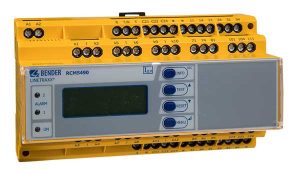
Our Advanced HRG uses state of the art technology. The NGRM700 serves as the primary neutral grounding resistor monitoring relay. The RCMS490 provides ground fault monitoring for up to twelve separate channels. Through the use of multiple devices, up to 3 separate busbars in 6 different substations, 120 feeders can be connected and protected with one MegaResistors HRG. With a combination of both, we provide a system with the best protection possible.
- Multi-channel ground fault protection
- Open and shortened monitoring of neutral grounding resistor through
- Resistance monitoring with passive and active measurement methods
- Current and voltage monitoring
- Functional even when de-energized
- Monitoring of current transformer
- AC and DC current monitoring
- Built in pulsing for handheld ground fault tracing
- Advanced harmonics analysis and filtering – no nuisance tripping
- Individually adjustable ground fault trip values
- Built in test and reset capability
- Password protection
- Configurable in English, French, Spanish, and German
- Modern HTML5 web interface: device alarm status and readings, accessible from any computer or phone
- Connects to any standard ethernet network
- Data logging: history memory for up to 1000 events
- Modbus/TCP third party device support
- Virtual setpoints – custom alarms for multiple devices using mathematical / logical operators (e.g. warning text message sent to personnel for intermittent ground fault)
- Additional Options
- Custom e-mail notifications on specified trigger events
- Unique naming of any devices
- Remote device configuration and settings access
- Visualizations of your system – automatically generated physical view
Different feeders in a large system have different priorities. The operation of some feeders are “mission-critical”, for economic, safety, or disaster-avoidance reasons.
Through high resistance grounding continuous operation can be maintained on any feeder in the event of a single ground fault. When a second or even third ground fault occurs in a different feeder, it is impossible to maintain continuous operation in the multiple feeders. By configuring your MegaResistors HRG, you can assign priorities to every single feeder depending on their importance to you.
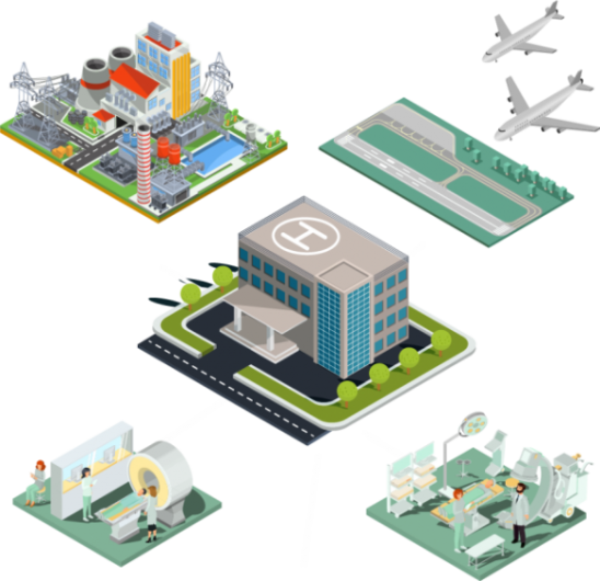
There are many examples of where this technology is exceptionally useful:
- In a data center: the feeder powering the air conditioning to prevent the overheating of equipment
- In an airport: the feeder powering the air traffic control room, with equipment and staff responsible for coordinating all traffic to prevent collisions
- In a hospital: any feeders powering life-support systems
- In a mine: a compressor providing oxygen delivery
Our HRG can assign 99 numbered priorities for up to 120 feeders.
Our standard unit comes with “Feeder Protection” which provides high and low priorities for feeders. For numbered priority and a touch screen interface select “Advanced Feeder Protection” in your quote request.
Configuration Options
Voltage
Please provide the line to neutral (L/N) voltage. Standard ratings are 277V (480V L/L), 347V (600V L/L), and 2400V (4160V L/L).
Current
The ground fault current. Typical ratings are 5 Amps or 10 Amps. A multi-tapped resistor is also possible, meeting the requirements for multiple ground fault currents at once (e.g. one at 2A, another at 5A, another at 10A).
Number of Feeders
The total number of feeders requiring protection/monitoring. Typically this number is all the “output lines” in a substation.
System Type
A Wye configuration is the standard, when there is a readily available neutral. When there is a Delta configuration, we must create a neutral with the use of a Zig-Zag (Neutral Grounding) transformer. If you select Delta, we can provide a Zig-Zag if we know your system rated kVA and primary voltage.
Control Power
The power supplied for the HRG control panel. We can provide 120VAC or 24VDC depending on your preference, our standard is 120VAC.
- Strobe Light: any time there is a ground fault a red strobe light will alert all staff
- Horn: any time there is a ground fault a horn / buzzer will alert all staff
- Heater: if the environment your HRG will be in is subject to cold temperatures, condensation can begin to accumulate and potentially damage parts. A condensation prevention heater can be installed to prevent this.
Additional Communication Modules:
- Custom email notifications
- Unique naming of devices
- Remote device configuration and settings access
- Instant system visualization
One HRG can be connected up to six substations with three busbars each. Each of these busbars require a separate resistor.
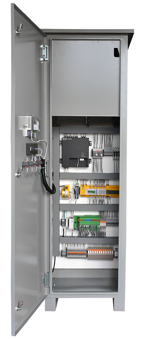
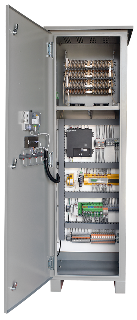
If you have a simple configuration with one busbar we recommend our hybrid enclosure configuration, which keeps the controls and resistors in one unit. We call this enclosure the “HR4”.
When one of the following applies:
- You require more than one busbar
- Or you prefer to keep the resistor separate from all controls
- Your voltage is higher than 600V L/L
We separate the units in to a “master” and “remote resistors”.
This configuration comes with the “HR3” enclosure and typically an “N3” enclosure for the resistor. On higher voltage resistors (above 600V), a larger enclosure is typically required for the resistor.
When connecting multiple substations, there will be interconnected panels for each substation, with separate resistors for each busbar.


