Braking Resistor
The purpose of a brake resistor is to help perform motor braking or overhauling by absorbing regenerated braking energy and dissipating it as heat with rheostatic resistors. This page is primarily focused on the application of dynamic braking resistors with low voltage drives.
Our braking resistors are designed, manufactured, and tested in Canada and are cULus listed. If you are replacing a resistor, or are getting one for a new application, get in touch with us. We have great prices, low lead times, and excellent service.


Enclosure Options
Our standard enclosure protection grade is NEMA 1.
We also offer NEMA 3R, 4, and 4X enclosures.
If you are an OEM or integrator and are using these resistors as part of a panel, we can offer just the resistor assembly without the enclosure.
Enclosures constructed for indoor use to provide a degree of protection to personnel against access to hazardous parts and to provide a degree of protection of the equipment inside the enclosure against ingress of solid foreign objects (falling dirt).
IP20
Protected against solid foreign objects of 12.5mm in diameter and greater. Not protected against water ingress.
Enclosures constructed for either indoor or outdoor use to provide a degree of protection to personnel against access to hazardous parts; to provide a degree of protection of the equipment inside the enclosure against ingress of solid foreign objects (falling dirt); to provide a degree of protection with respect to harmful effects on the equipment due to the ingress of water (rain , sleet, snow); and that will be undamaged by the external formation of ice on the enclosure.
IP23
Protected against solid foreign objects of 12.5mm in diameter and greater.
Water falling as a spray at any angle up to 60° from the vertical shall have no harmful effect.
Enclosures constructed for either indoor or outdoor use to provide a degree of protection to personnel against access to hazardous parts; to provide a degree of protection of the equipment inside the enclosure against ingress of solid foreign objects (falling dirt and windblown dust); to provide a degree of protection with respect to harmful effects on the equipment due to the ingress of water (rain, sleet, snow, splashing water, and hose directed water); and that will be undamaged by the external formation of ice on the enclosure.
IP56
Ingress of dust is not entirely prevented, but it must not enter in sufficient quantity to interfere with the satisfactory operation of the equipment; complete protection against contact.
Water projected in powerful jets (12.5mm nozzle) against the enclosure from any direction shall have no harmful effects.
A NEMA 4X enclosure is the exact same as a NEMA 4 enclosure, except it is constructed with corrosion resistant materials such as Stainless Steel 316. This type of enclosure is highly recommended if you will be operating this product within 5 kilometres of salt water, or you anticipate any other corrosive environmental elements.
A protective coating of zinc is applied to steel. The zinc provides cathodic protection due to its greater negative electrochemical potential, making it the metal of preference to be consumed (when rusting). It often shows an aesthetic feature known as spangle, crystallites inside the coating. All of our galvanized steel material meets specific ASTM coating standards.
The galvanized steel is then treated for painting with a non-metallic iron phosphate coating. This heavily improves paint adhesion and increases corrosion protection if the metal’s paint film is broken. After the steel has been phosphatized, it is then powder coated. Powder coating cures in heat, forming a “skin”. This creates a harder finish, tougher than conventional paint.
Galvanized steel is a generally cost-effective and reliable material to prevent corrosion and damage to your product.
The most widely used stainless steel is the “304” type, comprised of 18% chromium and 8% nickel. We also offer “316” and “316L” grade stainless steel, comprised of 18% chromium and 10% nickel.
Stainless steel is touted for its resistance to corrosion and staining, and low maintenance needs. If your product will be used in an environment subject to particular corrosive conditions then we recommend using stainless steel over galvanized steel.
Because stainless steel is comprised of chromium and nickel throughout the material itself, it provides corrosion resistance for a longer duration as it does not rely on a coating for protection. This leaves painting to be an an optional layer of protection. We generally use stainless steel unpainted unless otherwise specified.
Depending on their size and use, enclosures can be designed to be mounted in one of two ways:
Floor-mounted (e.g. top of a panel)
Wall-mounted (e.g. side of a panel)
If you have extensive braking power requirements and need multiple resistor assemblies, we can also provide large mounting frames for multiple units.
All of our product enclosures come with a standard ANSI 61 Gray, equivalent to RAL 7042.
We are happy to provide most standard RAL paint colors. If you are looking for a custom painted enclosure, let us know your RAL code.
Necessary Components
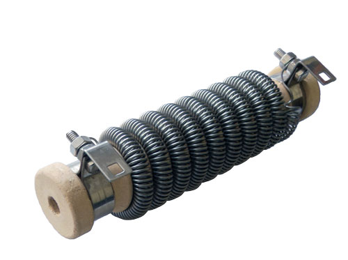
Wirewound resistive elements consists of an open helical stainless steel wire wrapped around a tubular porcelain core, allowing for fast and efficient cooling. In general wirewound resistive elements are ideal for low current conditions, offering excellent power dissipation, stable resistance, and shock-proofing.
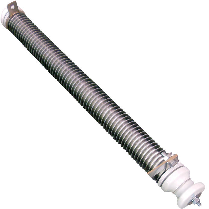
Edgewound resistive elements are strip type elements, essentially a stainless steel tape wound on tubular porcelain insulators. A rod is placed inside these resistive elements to form the resistive assembly. They are used in general for medium-level currents, touting shock-proofing, and compactness.
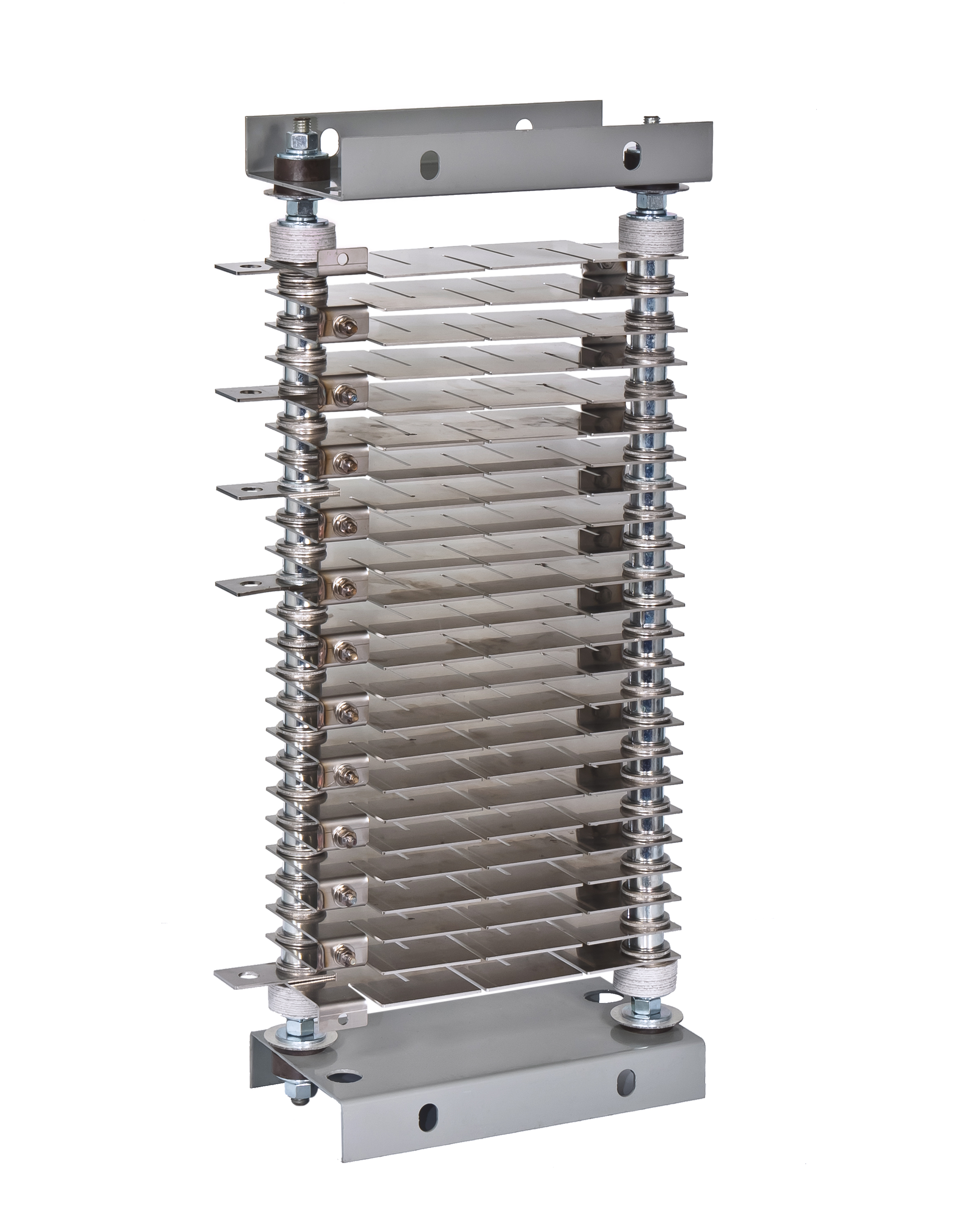
Generally used for low resistance and high current, grid resistors are made with punched steel sheet with holes at in each end for mounting. Grids are then stacked on insulated steel rods. Mica washers are inserted between grids for insulation, and the rods are mounted between steel end frames. To obtain the best electrical connection, we weld grids together.
For high power applications with high environmental requirements we can use tubular resistors.
Every dynamic braking resistor comes with built in thermal protection via a normally closed thermal switch.
If using a variable frequency drive, this thermal switch will automatically trip the drive in the case of a resistor malfunction or overheating.
You have the option of selecting a normally open thermal switch if you have a specific application requirement.
Useful Information
Fundamentally the purpose of a dynamic braking resistor is to slow down, quickly stop, or control a motor by absorbing the counter-electromotive force (CEMF) and keeping the drive and motor within safe tolerances to prevent damage and destruction.
When removed from a power supply, most DC motors will act as electrical generators due to their permanent magnets. If a resistor is then connected as a load, the energy produced by the rotational inertia of the DC motor will be dissipated by the resistor slowing down the motor. While AC motors do not have permanent magnets in their rotors, they do have an induced magnetic field created by the rotating magnetic field in the stator. The energy lost in the stator will backfeed into the variable frequency drive (VFD), which will rise the voltage on the DC bus in the VFD. The greater the difference between the output of the VFD and the rotor’s actual speed, the more energy will be fed into the VFD. If the VFD tries to brake the motor too quickly, the voltage will rise too much and damage the VFD. Most VFDs will shut down as a safety feature before this happens, and the motor will coast to a stop by friction alone. With appropriately sized braking resistors the motor can be stopped much more quickly without raising the voltage to unsafe levels.
Broken down into simpler pieces:
- Motors are designed to take electrical energy and convert it into mechanical energy for an application.
- When the application needs to brake, reverse, or overhaul a load, there will be CEMF (counter-electromotive force) generated. The mechanical energy will create electrical energy, making the motor effectively act as a generator.
- This excess regenerated energy must go somewhere; when the motor is controlled by a VFD, it will go to the VFD (specifically the DC bus).
- A braking transistor (usually part of a braking chopper) is connected to the DC bus to shunt (i.e. redirect) power to the Dynamic Braking Resistor when the DC bus voltage reaches a pre-determined level.
- The braking resistor will safely dissipate this energy as heat.
Brake resistors are always designed with two specifications, average braking power, and resistance.
Braking power
Peak braking power is commonly approximated by taking the motor horsepower (in watts) and the braking torque and multiplying them. For example a 20HP motor with a 150% braking torque would give you a peak power of: (20*745.7*1.5) = 14914 Watts
The most correct method of getting braking power (for deceleration applications) is more complicated and time-consuming, we describe this in more detail on our Braking Resistor Calculator page. Essentially this requires accounting for the inertia of the load, inertia of the motor, any gearing effects, starting motor speed, and desired ending motor speed.
Peak braking power must be translated into average braking power by using the duty cycle. Please refer to the “Braking resistor duty cycles” section below for more information on duty cycles. Assume our cycle is 20 seconds on, 40 seconds off.
For deceleration applications:
14914 watts * (20/(40+20)) * (1/2) = 2486 watts
For overhauling applications (double the power):
14914 watts * (20/(40+20)) = 4971 watts
Resistance
Braking resistors with smaller ohmic values will help motors stop faster but will also dissipate more heat.
The most important variable is minimum resistance, which is always determined by the braking chopper / transistor’s capacity. This info will come from the drive OEM.
Maximum resistance is calculated by accounting for the DC bus operating voltage and peak braking power.

The following diagram displays the relationship between speed, torque (and braking torque), power (and braking power), and regenerated power.
There is no industry consensus on standard duty cycles. Each brake resistor or drive manufacturer has their own standards. Ultimately this doesn’t matter; typical duty cycles are presented for what someone anticipates a “standard” or “typical” application is.
For market reasons, drive manufacturers typically specialize in certain applications (for example, one may focus on HVAC industry drives, another may focus on crane control). Inevitably this results in “typical” application duty cycles based on what the manufacturer specializes in.
Generally, these are presented in various formats, which can all mean the exact same thing:
- 30 seconds on, 30 seconds off
- 30 seconds on, 60 second cycle
- 50% duty, 60 second cycle

The above diagram depicts an application with a trapezoidal movement profile. Here the cycle time is 2.5 seconds, and the braking time or time on is 0.5s, which gives us a duty cycle of 20%. The best way to size a brake resistor is always based on your specific application. This will ensure your resistor is cost-effective, and won’t fail because it is under-powered. We’ve got a helpful tool to help you size a braking resistor for your application you can find here.
The downside to this method is that you may not know all the details of your application ahead of time, or you simply don’t have the time. In this case we recommend you select your drive manufacturer from the “Browse by Drive Manufacturer” section, and choose a brake resistor based on the cross-reference lists that matches your drive model based on recommendations from the manufacturer.
There are two different braking types or categories that significantly affect the sizing of a braking resistor.

Deceleration / Dynamic Braking
If you have a motor running and simply want to brake it, this is referred to as deceleration. The braking power peaks at the beginning and gradually decreases to 0 (which will occur at your desired decelerated speed). You are dynamically converting a rotational energy into electrical energy, which allows faster braking than just letting the motor coast to a stop. Sometimes this is also referred to as a “Horizontal Load”.
The average braking power is half the peak braking power.
Application examples: conveyors, trolleys, gantry cranes
Overhauling Load / Holding
Your braking application is countering an external force, usually gravity, and braking power is constant. Here your rotational energy is naturally converting into electrical energy, and you are diverting it away from the motor and drive. Sometimes this is also referred to as a “Vertical Load”.
The average braking power is the same as the peak braking power.
Application examples: cranes, hoists, elevators
The application of a DC bus has extended and evolved as VFD technology has. In the context of braking resistors, the DC bus is a discharge medium for regenerated energy.
A brake chopper or braking chopper consists of some electronic components whose function is to shunt or redirect power to the braking resistor when the VFD voltage exceeds a certain threshold. They use a simple on-off control.
Many manufacturers use braking transistor and brake chopper interchangeably.
A chopper is essential “the brains” of a braking resistor, and is a slave to the DC bus.

The above diagram displays the relationship between the DC bus in a VFD, the brake transistor, and the brake resistor.
Although we are not a manufacturer of brake choppers, we’ve worked to develop relationships with reputable suppliers and can help provide you a chopper suited towards your drive and required braking power.
The most common applications that require dynamic braking are ones that typically generate the most braking energy. This usually occurs as a nature of the application, i.e. frequent braking or overhauling loads. Many projects will fit a braking resistor for emergency stopping reasons as well.
These applications commonly include:
- Centrifuges
- Conveyors
- Cranes
- Cutting machines, shears, saws
- Fans
- Pumps
- Reversing
Dynamic Braking is also used in locomotive applications as an essential part of a transit system. This page does not discuss Dynamic Braking Resistors in this context.
- AC Drive: device used to control the speed of an electrical motor by changing the frequency of the electrical supply to the motor
- Variable Frequency Drive (VFD): refers to AC drives
- Variable Speed Drive (VSD): refers to either AC drives or DC drives
- Adjustable Frequency Drive (AFD): refers to AC drives
- Adjustable Speed Drive (ASD): refers to either AC drives or DC drives
- Frequency Inverter: refers to AC drives
- Servo drive: similar to a VFD, but used for motion control applications such as robot arms
- Brake chopper: a device used to activate a braking resistor
- Braking transistor: part of a brake chopper, or used interchangeably with brake chopper
- DC bus: capacitators inside the VFD with multiple functions
- Dynamic Braking Resistor (DBR): the correct and complete term used to refer to this product
- Braking Resistor: short form for Dynamic Braking Resistor
- Brake Resistor: used interchangeably with Dynamic Braking Resistor
- Dynamic Braking: refers to the process of performing braking through electrical rather than mechanical means
- VFD braking: used to refer to the specific function of using a DBR with a VFD
Benefits
- Faster braking of DC and AC motors
- Lower wear and tear of friction braking components
- Longer equipment life
- Safe voltage levels
- Eliminate risk of thermal runaway due to friction brakes
- Improved service reliability
- Designed to absorb thermal expansions and contractions